Raspberry Pi Fan Driver (Part 2)
In this post we are going to add some GPIO handling for our driver.

Part 2 (GPIO Handling)
This part updates the previous starter driver with GPIO support. Driver would be able to control any available GPIO and be configurable from user-space via character driver defined earlier.
The blog is not written by a professional, so there may be inaccuracies. Please verify the important information.
Modularisation
This is a proper place to divide our driver into several modules, where each one will handle some specific task, while the main driver.c file will define the main initialisation part. It also helps with readability and makes it more clear what part of the code handles. So let’s create a new gpio.c file, where we will define all GPIO related functions.
1
2
3
4
5
6
7
.
├── compile_commands.json
└── src
    ├── driver.c
    ├── fan.h
    ├── gpio.c
    └── Makefile
Since we wish to call functions defined in gpio.c it would be great to declare them in the header file fan.h, which will be available for all our modules:
1
2
3
4
5
6
7
8
9
/* Header file for Raspberry Pi driver. File: fan.h */

#ifndef __RPI4F__
#define __RPI4F__

#define DEVICE_NAME "rpifan"
#define CLASS_NAME "fan"

#endif
Before declaring any files it is good to move all driver’s related definitions like DEVICE_NAME and CLASS_NAME to the header. do not forget to include the header for all of your modules:
1
2
3
4
5
6
7
8
9
10
11
12
/* File: driver.c */
#include<linux/kernel.h>
#include<linux/module.h>
#include<linux/cdev.h>
#include<linux/fs.h>

#include"fan.h"

#define KBUF_SIZE 4

/**************** Driver data fields ****************/
...
Before manipulating with GPIOs we shall define which data type will be used to point out which GPIO pin shall be used for our fan and probably think about later PWM support.
The
KBUF_SIZEsymbol might not be the best option to move to the header file as it only defines the size of buffer, that is being used when copying data from user and to user, inside therpfan_readandrpfan_writefunctions. Symbols which are more local are better to not be moved into a public header file.
The Configuration Data Type
To decide about the data type, let’s take a glance on Raspberry Pi GPIO header:
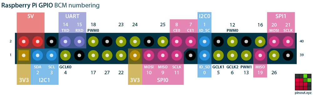 Raspberry Pi 40-pin Header
Here are the two 5V pins, primarily used for the fan, along with the 3.3V pin and several GND pins. Sometimes these pins might be needed for other purposes, so we want the ability to set the remaining pins high in order to connect our fan.
Some of those pins are reserved for advanced use, like UART, SPI, I$^2$C etc., however the driver must allow to use any of available pins.
This pinout is taken from pinout.xyz. It provides a precise description of each pin and their eventual function. This page also provides pinouts for different Raspberry Pi HATs, pHats and addons.
Most1 of Raspberry Pi platforms has this 40-pin header, so the driver would be compatible with all of them, since Linux would handle most of the differences. With all power pins ignored, that leaves us with 28 configurable GPIO pins, so 5 bits would be enough to define all of them. If we wish to store the configuration in one byte, then three free bits are left for the PWM states.
block-beta
	columns 4
	PWM["PWM\nSTATE"]
	GPIO["GPIO PIN"]:3
	PWM_BITS["3 BITS"]
	GPIO_BITS["5 BITS (LOW)"]:3

	block:PWM_DUTY_CYCLE:1
		columns 1
		PWM_S1["100%"]
		PWM_S2["88%"]
		PWM_S3["76%"]
		PWM_S4["64%"]
		PWM_S5["52%"]
		PWM_S6["40%"]
		PWM_S7["28%"]
		PWM_S8["16%"]
	end

	block:GPIO_VALUES:3
		columns 4
		GPIO_S0["PIN 0"]
		GPIO_S1["PIN 1"]
		GPIO_S2["PIN 2"]
		GPIO_S3["PIN 3"]
		GPIO_S4["PIN 4"]
		GPIO_S5["PIN 5"]
		GPIO_S6["PIN 6"]
		GPIO_S7["PIN 7"]
		GPIO_S8["PIN 8"]
		GPIO_S9["PIN 9"]
		GPIO_S10["PIN 10"]
		GPIO_S11["PIN 11"]
		GPIO_S12["PIN 12 PWM0"]
		GPIO_S13["PIN 13 PWM1"]
		GPIO_S14["PIN 14"]
		GPIO_S15["PIN 15"]
		GPIO_S16["PIN 16"]
		GPIO_S17["PIN 17"]
		GPIO_S18["PIN 18 PWM0"]
		GPIO_S19["PIN 19 PWM1"]
		GPIO_S20["PIN 20"]
		GPIO_S21["PIN 21"]
		GPIO_S22["PIN 22"]
		GPIO_S23["PIN 23"]
		GPIO_S24["PIN 24"]
		GPIO_S25["PIN 25"]
		GPIO_S26["PIN 26"]
		GPIO_S27["PIN 27"]

		GPIO_S28["RESERVED"]
		GPIO_S29["RESERVED"]
		GPIO_S30["RESERVED"]
		GPIO_S31["RESERVED"]
	end

	PWM --> PWM_BITS
	GPIO --> GPIO_BITS
	PWM_BITS --> PWM_DUTY_CYCLE
	GPIO_BITS --> GPIO_VALUES

	classDef gpioI2C fill:blue,stroke:#333,stroke-width:2px
	classDef gpioSPI fill:magenta,stroke:#333,stroke-width:2px
	classDef gpioUART fill:purple,stroke:#333,stroke-width:2px
	classDef gpioPWM fill:green,stroke:#333,stroke-width:2px
	classDef reserved fill:red,stroke:#333,stroke-width:4px

	style PWM_S8 fill:#004c00,stroke:#333,stroke-width:2px
	style PWM_S7 fill:#006600,stroke:#333,stroke-width:2px
	style PWM_S6 fill:#008000,stroke:#333,stroke-width:2px
	style PWM_S5 fill:#009900,stroke:#333,stroke-width:2px
	style PWM_S4 fill:#00b300,stroke:#333,stroke-width:2px
	style PWM_S3 fill:#00cc00,stroke:#333,stroke-width:2px
	style PWM_S2 fill:#00e600,stroke:#333,stroke-width:2px
	style PWM_S1 fill:#00ff00,stroke:#333,stroke-width:2px

	class GPIO_S28,GPIO_S29,GPIO_S30,GPIO_S31 reserved
	class GPIO_S0,GPIO_S1,GPIO_S2,GPIO_S3 gpioI2C
	class GPIO_S7,GPIO_S8,GPIO_S9,GPIO_S10,GPIO_S20,GPIO_S19,GPIO_S21 gpioSPI
	class GPIO_S14,GPIO_S15 gpioUART
Block diagram above shows the data structure of the global configuration variable that we are going to use. 5 bits could easily handle all 28 GPIO pins, while the rest would allow us to define 8 different PWM states.
Some of those pins are most likely to be used for other purposes, so it is up to driver’s developer to decide, which pins shall be allowed for fan’s use. Another way would be show a warning message, when some important pins, like
ID_EEPROMpins, are being used. Our driver would allow to use any of available GPIO pins.
From the diagram we can also see what PWM states can be used. For example there is no need in 0% value, because it just turns off the fan, the same goes for values lower than 16%.
Those values were obtained in a following way: \(\begin{equation} \label{eq:eq1} STEP=\frac{MAX - MIN}{2^{B}}=\frac{100\%-10\%}{2^{3}}=\frac{90\%}{8}\approx12\% \end{equation}\)
The equation above \eqref{eq:eq1} is a way of calculating the step between different states, for bits, which are reserved for the PWM. For example if the step was 5%, we won’t even see the difference in how our fan spins.
It is not necessary to fit all configuration in just a single byte, but it is done so here because the amount of configuration possible for this driver is rather small and more advanced configuration features will be done sooner with
IOCTLcalls. It is ok to store more data, even whole strings that define which PWM state shall be used, but that might lead to bigger code and more used space, which is not necessary for such small driver.
Since we expect our data to be written in one byte, let’s define a new data type within the header file, so it can be used in all driver’s modules. One way would be to simply define it as follows: static uint8_t fan_config;, but then we would have to use bit-masks to read and write proper bits for GPIO and PWM handling. There is a better way of doing that:
1
2
3
4
5
6
7
8
9
10
11
12
13
14
15
16
17
18
19
20
21
22
23
24
25
26
27
28
29
30
/* file: fan.h */

#ifndef __RPI4F__
#define __RPI4F__

#define DEVICE_NAME "rpifan"
#define CLASS_NAME "fan"

// Default PWM option
#define PWM_OFF 0b111
// Adaptive PWM. The value is defined based on the CPU load.
#define PWM_ADP 0b000

#include<linux/types.h>

/*
 * Fan configuration structure
 *
 * Lower 5 bits for 28 available GPIO pins (the rest are reserved). Three bits for PWM mode configuration.
 * */
union fan_config {
    uint8_t bytes;

    struct {
        uint8_t gpio_num: 5;
        uint8_t pwm_mode: 3;
    };
};

#endif
We can create a union and make the C compiler handle all bit-wise magic for us, which he definitely does much better. This might look like too much for a single 8-bit value, and maybe it is, but for more advanced structures, which are usually packed data like some hardware descriptors or tables it is the best way to save ourselves from the upcoming errors. Notice that we also defined the PWM_OFF and PWM_ADP symbols for use in different modules.
The fan_config.bytes is a way to access all 8-bits like a one chunk of memory. fan_config.gpio_num and fan_config.pwm_mode allows to access only reserved bits for each one, which is much easier and cleaner to read than bit masking.
The anonymous struct is used here for a reason. Without it, the C compiler would perceive
gpio_numandpwm_modeas if they were symbols pointing to the same memory location. In this specific situation, the first three bits of both would have collided. If this is not yet clear, it is recommended to review the differences between unions and structures, and how the C compiler interprets them.
GPIO Related Code
Now when we know about the data we are going to pass to our function, it is time to declare it:
1
2
3
4
5
6
7
8
9
10
11
12
13
14
/* file: fan.h */

...

/* Sets the new GPIO while parsing values and returning obtained errors */
int set_gpio(union fan_config *, uint8_t);
/* Initializes the first available GPIO in the system. */
int init_gpio(union fan_config *);
/* Frees the current GPIO */
void free_cgpio(union fan_config *);

...

#endif
There will be three functions: the first will change the GPIO pin to a new one based on the old pin and the current configuration. The second is an initialization function, used when we don’t know which GPIO pin is currently free and can be used for our fan; it will pick the first available one. Last one just frees the pin that is currently used.
The implementation of each is added to gpio.c module like so:
1
2
3
4
5
6
7
8
9
10
11
12
13
14
15
16
17
18
19
20
21
22
23
24
25
26
27
28
29
30
31
32
33
34
35
36
37
38
39
40
41
42
43
44
45
46
47
48
49
50
51
52
53
54
55
56
57
58
59
60
61
62
63
64
65
66
67
68
69
70
71
72
73
74
75
76
77
78
79
80
81
82
83
84
85
86
87
88
89
90
91
92
93
94
95
96
97
/* file: gpio.c */

#include<linux/module.h>
#include<linux/gpio.h>
#include"fan.h"

#define OUT 0
#define LOW 0
#define HIGH 1

// The name of our acquired GPIO pin.
#define GPIO_NAME "FAN_GPIO"
// First GPIO pin
#define GPIO_MIN 2
// Amount of available GPIO pins.
#define GPIO_AMOUNT 28

// All raspberry pi GPIO pins, that can be used as a PWM.
#define PWM_GPIOS 12:case 13:case 18:case 19
// Physical pins (27, 28) are reserved for advanced use.
#define RESERVED 0 ... 1
// Out of range. Litteraly everything that is 28 or greater.
#define OOR GPIO_AMOUNT ... 255

/* sets the new GPIO while parsing values and returning obtained errors */
int set_gpio(union fan_config *config, uint8_t old_gpio) {
    uint8_t new_gpio = config->gpio_num;
    // Parsing the configuration value.
    switch (new_gpio) {
        case OOR:
            pr_err("%s: ERROR: GPIO_%d is not a proper pin, ignoring...\n", THIS_MODULE->name, new_gpio);
            return -EINVAL;
        case RESERVED:
            pr_warn("%s: WARN: GPIO_%d is reserved for advanced use and is not recomended to use (ID_EEPROM) pins.\n",
                    THIS_MODULE->name, new_gpio);
        case PWM_GPIOS:
            // TODO! handle the PWM accordingly.
            break;
        default:
            pr_warn("%s: WARN: GPIO_%d is not a PWM pin. PWM configuration will be ignored.\n",
                THIS_MODULE->name, new_gpio);

    }

    // Changing the current GPIO state
    if(old_gpio != new_gpio) {
        if(gpio_request(new_gpio, GPIO_NAME) < 0) {
            pr_err("%s: ERROR: GPIO_%d request failed.\n", THIS_MODULE->name, new_gpio);
            return -EACCES;
        }

        gpio_set_value(old_gpio, LOW);
        gpio_free(old_gpio);

        gpio_direction_output(new_gpio, OUT);
        gpio_set_value(new_gpio, HIGH);
    }

    pr_info("%s: New configuration is provided: GPIO_%d, PWM_MODE_%d\n",
            THIS_MODULE->name, new_gpio, config->pwm_mode);

    return 0;
}

/* Initialises the first available GPIO in the system. */
int init_gpio(union fan_config *config) {
    uint8_t gpio = GPIO_MIN;
    for(; gpio < GPIO_AMOUNT; ++gpio) {
        if(gpio_is_valid(gpio)) {
            // When a valid GPIO is found, requesting it.
            if(gpio_request(gpio, GPIO_NAME) < 0) {
                pr_err("%s: ERROR: GPIO_%d request failed...\n", THIS_MODULE->name, gpio);
            } else break;
        }
    }

    // This check is true if all GPIO requests would fail.
    if(gpio == GPIO_AMOUNT) {
        pr_err("%s: Requests failed. All pins are in use, aborting..\n", THIS_MODULE->name);
        return -EACCES;
    }

    gpio_direction_output(gpio, OUT);
    gpio_set_value(gpio, HIGH);

    config->pwm_mode = PWM_OFF;
    config->gpio_num = gpio;

    return 0;
}

/* Frees the current GPIO */
void free_cgpio(union fan_config *config) {
    gpio_set_value_cansleep(config->gpio_num, LOW);
    gpio_free(config->gpio_num);
}
There is a lot to handle at once, but let’s interpret what is going on one by one:
1
2
3
4
5
6
7
8
9
10
11
12
13
14
15
16
17
18
19
20
/* file: gpio.c */

#define OUT 0
#define LOW 0
#define HIGH 1

// The name of our acquired GPIO pin.
#define GPIO_NAME "FAN_GPIO"
// First GPIO pin
#define GPIO_MIN 2
// Amount of available GPIO pins.
#define GPIO_AMOUNT 28

// All raspberry pi GPIO pins, that can be used as a PWM.
#define PWM_GPIOS 12:case 13:case 18:case 19
// Physical pins (27, 28) are reserved for advanced use.
#define RESERVED 0 ... 1
// Out of range. Litteraly everything that is 28 or greater.
#define OOR GPIO_AMOUNT ... 255
...
Most of them are straightforward, but some probably do require some additional explanation:
#define GPIO_NAME "FAN_GPIO"- This is a name that we give to our GPIO when we acquire it. It does not play too much of a role, but it must be provided anyway. This name can be seen in a list of all GPIOs, by reading data from debugfs2.#define PWM_GPIOS 12:case 13:case 18:case 19- Yes that might look ugly and unreadable at first, but it make it clean inside the switch statement inset_gpiofunction. Preprocessor is just a program that works with text, so this chunk is okay.#define OOR GPIO_AMOUNT ... 255- Convenient ranges in switch statements do exist!!!3
Now let’s examine the first function:
1
2
3
4
5
6
7
8
9
10
11
12
13
14
15
16
17
18
19
20
21
22
23
24
25
26
27
28
29
30
31
32
33
34
35
36
37
38
39
40
41
42
43
44
45
46
/* file: gpio.c */

...

/* sets the new GPIO while parsing values and returning obtained errors */
int set_gpio(union fan_config *config, uint8_t old_gpio) {
    uint8_t new_gpio = config->gpio_num;
    // Parsing the configuration value.
    switch (new_gpio) {
        case OOR:
            pr_err("%s: ERROR: GPIO_%d is not a proper pin, ignoring...\n", THIS_MODULE->name, new_gpio);
            return -EINVAL;
        case RESERVED:
            pr_warn("%s: WARN: GPIO_%d is reserved for advanced use and is not recomended to use (ID_EEPROM) pins.\n",
                    THIS_MODULE->name, new_gpio);
        case PWM_GPIOS:
            // TODO! handle the PWM accordingly.
            break;
        default:
            pr_warn("%s: WARN: GPIO_%d is not a PWM pin. PWM configuration will be ignored.\n",
                THIS_MODULE->name, new_gpio);

    }

    // Changing the current GPIO state
    if(old_gpio != new_gpio) {
        if(gpio_request(new_gpio, GPIO_NAME) < 0) {
            pr_err("%s: ERROR: GPIO_%d request failed.\n", THIS_MODULE->name, new_gpio);
            return -EACCES;
        }

        gpio_set_value(old_gpio, LOW);
        gpio_free(old_gpio);

        gpio_direction_output(new_gpio, OUT);
        gpio_set_value(new_gpio, HIGH);
    }

    pr_info("%s: New configuration is provided: GPIO_%d, PWM_MODE_%d\n",
            THIS_MODULE->name, new_gpio, config->pwm_mode);

    return 0;
}

...
The function has two parameters: the current fan’s config and an old GPIO pin that was used before. The latter one is required to free the pin that is no longer needed, so that other drivers could use it.
The first part is a switch statement mentioned earlier. It just parses the current value of config->gpio_num and prints a proper message based on the value. Here the symbols defined above make it readable and clean.
Since PWM is not supported yet, we add a TODO! label for future selves. Last important part in this chunk is the out of range condition. There we print an error message to dmesg and also returning an error code -EINVAL, indicating that the argument passed to a function is out of range.
1
2
3
4
5
6
7
8
9
10
11
12
13
14
15
16
17
18
19
20
21
22
23
24
25
26
27
28
29
30
31
/* file: gpio.c */

...

/* sets the new GPIO while parsing values and returning obtained errors */
int set_gpio(union fan_config *config, uint8_t old_gpio) {

	...

    // Changing the current GPIO state
    if(old_gpio != new_gpio) {
        if(gpio_request(new_gpio, GPIO_NAME) < 0) {
            pr_err("%s: ERROR: GPIO_%d request failed.\n", THIS_MODULE->name, new_gpio);
            return -EACCES;
        }

        gpio_set_value(old_gpio, LOW);
        gpio_free(old_gpio);

        gpio_direction_output(new_gpio, OUT);
        gpio_set_value(new_gpio, HIGH);
    }

    pr_info("%s: New configuration is provided: GPIO_%d, PWM_MODE_%d\n",
            THIS_MODULE->name, new_gpio, config->pwm_mode);

    return 0;
}

	...
The next part checks if the new GPIO pin is not the same as a previous one. If so, then we request it via gpio_request function. It requires two parameters: pin’s number and name. If the pin is used by another piece of software, request would fail and we shall show the error message with a proper error code: -EACCES, which indicates that a resource is busy.
Functions like
gpio_request,gpio_freeand others alike are now considered legacy ones and shall be replaced with newer descriptor API. For now it is easier to start with this one, since it will work on most kernels, except the newest ones, but later such thing must be refactored or configured out for a specific Linux version.
Afterwards we put the old PIN LOW with gpio_set_value, which was HIGH previously, and then freeing it with gpio_free. From that moment any other driver that is willing to acquire this pin can do it freely. Then new pin must be set as output with gpio_direction_output and set logically HIGH.
Those functions like
gpio_set_valueare meant to be used in an atomic context, which means that the GPIO can be accessed through a simple read/write operation. This is true for GPIO controllers that are embedded in the platform’s SoC. However for some external ones, like I$^2$C or SPI GPIO expanders, alternative functions with the_cansleepsuffix must be used.
The initialization function does not have initial data about which GPIO should be used, moreover the configuration provided to the function will be uninitialized and it is a job of this function to properly find a free GPIO.
1
2
3
4
5
6
7
8
9
10
11
12
13
14
15
16
17
18
19
20
21
22
23
24
25
26
27
28
29
30
31
32
33
/* file: gpio.c */

...

/* Initialises the first available GPIO in the system. */
int init_gpio(union fan_config *config) {
    uint8_t gpio = GPIO_MIN;
    for(; gpio < GPIO_AMOUNT; ++gpio) {
        if(gpio_is_valid(gpio)) {
            // When a valid GPIO is found, requesting it.
            if(gpio_request(gpio, GPIO_NAME) < 0) {
                pr_err("%s: ERROR: GPIO_%d request failed...\n", THIS_MODULE->name, gpio);
            } else break;
        }
    }

    // This check is true if all GPIO requests would fail.
    if(gpio == GPIO_AMOUNT) {
        pr_err("%s: Requests failed. All pins are in use, aborting..\n", THIS_MODULE->name);
        return -EACCES;
    }

    gpio_direction_output(gpio, OUT);
    gpio_set_value(gpio, HIGH);

    config->pwm_mode = PWM_OFF;
    config->gpio_num = gpio;

    return 0;
}

...
Here we simply iterating over each GPIO index and checking if it’s valid with gpio_is_valid. Then trying to request it until we find the first available free pin.
The if statement below checks if we have tried to access all available GPIO pins. If so, then all of them are busy for some reason and we cannot proceed further, therefore returning -EACCES value. If everything is well, then we shall acquire the pin, just like we did in the previous function with gpio_direction_output and gpio_set_value.
In the end we can see why union can be useful, because just by writing the fields of some value the C compiler will generate code that enforces the specified bit field width:
1
2
3
4
...
	config->pwm_mode = PWM_OFF;
    config->gpio_num = gpio;
...
The last function free_cgpio is straightforward.
1
2
3
4
5
/* Frees the current GPIO */
void free_cgpio(union fan_config *config) {
    gpio_set_value_cansleep(config->gpio_num, LOW);
    gpio_free(config->gpio_num);
}
Wrapping Things Up
Since we have our GPIO handling, the only thing left is to call it from the main driver.c module and also change the character device related functions, to actually copy content to the configuration structure from user and the other way around.
1
2
3
4
5
6
7
8
9
10
11
12
13
14
15
16
17
18
19
20
21
/* file: driver.c */

#include<linux/kernel.h>
#include<linux/module.h>
#include<linux/cdev.h>
#include<linux/fs.h>

#include"fan.h"

#define KBUF_SIZE 4

/**************** Driver data fields ****************/
static struct class *dev_class;
static struct cdev rpfan_gpio_cdev;
static struct file_operations fops;
static union fan_config config;     // new.

// The kbuf is now a local variable.
dev_t dev = 0;
/****************************************************/
...
We must define a static configuration variable, so it can be then passed to every function that is using it. Notice that the kbuf is not a global variable anymore.
1
2
3
4
5
6
7
8
9
10
11
12
13
14
15
16
17
18
/* file: driver.c */
...
/* Reading the current data configuration. */
static ssize_t rpfan_read(struct file *file, char __user *buf, size_t size, loff_t *off) {
    char kbuf[KBUF_SIZE];                               // new.
    snprintf(kbuf, KBUF_SIZE, "%u", config.bytes);      // new.
    ssize_t len = min(KBUF_SIZE - *off, size);

    if(copy_to_user(buf, &kbuf + *off, len)) {
        pr_err("%s: Failed to provide config data to the user.\n", THIS_MODULE->name);
        return -EFAULT;
    }
    pr_debug("%s: Data read succesfully: %s\n", THIS_MODULE->name, kbuf);

    *off += len;
    return len;
}
...
The buffer is moved here to the rpfan_read function. Here the snprintf function is used to convert a uint8_t into a text format, so we can send it to user. It first saves it to the kbuf buffer, and then copies the data to user from that buffer.
1
2
3
4
5
6
7
8
9
10
11
12
13
14
15
16
17
18
19
20
21
22
23
24
25
26
27
28
/* file: driver.c */
...
/* Writing new configuration to the character device. */
static ssize_t rpfan_write(struct file *file, const char *buf, size_t len, loff_t *off) {
    uint8_t gpio_old = config.gpio_num;       // new.

    if(len > KBUF_SIZE) {
        pr_err("%s: Invalid data size\n", THIS_MODULE->name);
        return -EINVAL;
    }

	/* new */
    // Converting to u8.
    if(kstrtou8_from_user(buf, len, 10, &config.bytes)) {
        pr_err("%s: ERROR: Unconvertable u8 value: %s\n", THIS_MODULE->name, buf);
        return -EINVAL;
    }

    uint8_t ret;
    if((ret = set_gpio(&config, gpio_old)) < 0) {
        return ret;
    }
    /* new */

    return len;
}

...
In the write function we first read the currently used GPIO and write it to old_gpio variable. Then we use the kstrtou8_from_user function to copy data from user and convert it to uint8_t format right away.
The
kstrtou8_from_userfunctions and and its counterparts can also convert data written in text format in different bases. For example, here we expect a decimal input, and therefore, we use base 10.
Then it is time to call the previously defined set_gpio function and try to swap GPIOs. If something will go wrong, we would forward the return status code, so that user would see the error.
1
2
3
4
5
6
7
8
9
10
11
12
13
14
15
16
17
18
19
20
21
22
23
24
25
26
27
28
29
30
31
32
33
34
35
36
37
38
39
40
41
42
43
44
45
46
47
48
49
/* file: driver.c */
...
/* Environment initialization. */
static int __init rpfan_driver_init(void) {
     // RPi fan character device region.
    if(alloc_chrdev_region(&dev, 0, 1, DEVICE_NAME) < 0) {
        pr_err("%s: ERROR: Unable to allocate major number, aborting...\n", THIS_MODULE->name);
        goto _unreg;
    }

    pr_debug("%s: DEBUG: Major = %d, Minor = %d\n", THIS_MODULE->name, MAJOR(dev), MINOR(dev));
    cdev_init(&rpfan_gpio_cdev, &fops);

    // RPi character device driver.
    if(cdev_add(&rpfan_gpio_cdev, dev, 1) < 0) {
        pr_err("%s: ERROR: Unable to add the character device for raspberry pi fan.\n", THIS_MODULE->name);
        goto _cdev;
    }

    // Creating a class
    if(IS_ERR(dev_class = class_create(THIS_MODULE, CLASS_NAME))) {
        pr_err("%s: ERROR: Unable to create the structure class.\n", THIS_MODULE->name);
        goto _class;
    }

    // Spawning the device
    if(IS_ERR(device_create(dev_class, NULL, dev, NULL, DEVICE_NAME))) {
        pr_err("%s: ERROR: Unable to create the device.\n", THIS_MODULE->name);
        goto _dev;
    }

    // If everything is ok, trying to obtain one of the first available pins.
    if(init_gpio(&config) < 0) goto _dev;    // new.

	pr_info("%s: Fan driver properly initialized.\n", THIS_MODULE->name);
	return 0;

_dev:
    device_destroy(dev_class, dev);
_class:
    class_destroy(dev_class);
_cdev:
    cdev_del(&rpfan_gpio_cdev);
_unreg:
    unregister_chrdev_region(dev, 1);

    return -1;
}
...
In initialization function we must add init_gpio to acquire the first GPIO.
1
2
3
4
5
6
7
8
9
10
11
12
13
/* file: driver.c */
...
/* Unloading the module. */
static void __exit rpfan_driver_exit(void) {
    free_cgpio(&config);  // new.

    device_destroy(dev_class, dev);
    class_destroy(dev_class);
    cdev_del(&rpfan_gpio_cdev);
    unregister_chrdev_region(dev, 1);
    pr_info("%s: Fan driver closed.\n", THIS_MODULE->name);
}
...
The last change would be in the module __exit function. When driver is unloaded, we have to free a pin that was previously used.
1
2
3
4
5
6
7
8
9
10
11
12
13
14
15
16
17
18
19
20
21
22
23
24
25
26
27
28
29
30
31
32
33
34
35
36
37
38
39
40
41
42
43
44
45
46
47
48
49
50
51
52
53
54
55
56
57
58
59
60
61
62
63
64
65
66
67
68
69
70
71
72
73
74
75
76
77
78
79
80
81
82
83
84
85
86
87
88
89
90
91
92
93
94
95
96
97
98
99
100
101
102
103
104
105
106
107
108
109
110
111
112
113
114
115
116
117
118
119
120
121
122
123
124
125
126
127
128
129
130
131
132
133
134
135
136
137
138
139
140
141
142
143
144
145
/* file: driver.c */

#include<linux/kernel.h>
#include<linux/module.h>
#include<linux/cdev.h>
#include<linux/fs.h>

#include"fan.h"

#define KBUF_SIZE 4

/**************** Driver data fields ****************/
static struct class *dev_class;
static struct cdev rpfan_gpio_cdev;
static struct file_operations fops;
static union fan_config config;     // new.

// The kbuf is now a local variable.
dev_t dev = 0;
/****************************************************/

/* Character device open. */
static int rpfan_open(struct inode *inode, struct file *file) {
    pr_debug("%s: Configuration file opened.\n", THIS_MODULE->name);
    return 0;
}

/* Character device closed. */
static int rpfan_release(struct inode *inode, struct file *file) {
    pr_debug("%s: Configuration file closed.\n", THIS_MODULE->name);
    return 0;
}

/* Reading the current data configuration. */
static ssize_t rpfan_read(struct file *file, char __user *buf, size_t size, loff_t *off) {
    char kbuf[KBUF_SIZE];                               // new.
    snprintf(kbuf, KBUF_SIZE, "%u", config.bytes);      // new.
    ssize_t len = min(KBUF_SIZE - *off, size);

    if(copy_to_user(buf, &kbuf + *off, len)) {
        pr_err("%s: Failed to provide config data to the user.\n", THIS_MODULE->name);
        return -EFAULT;
    }
    pr_debug("%s: Data read succesfully: %s\n", THIS_MODULE->name, kbuf);

    *off += len;
    return len;
}

/* Writing new configuration to the character device. */
static ssize_t rpfan_write(struct file *file, const char *buf, size_t len, loff_t *off) {
    uint8_t gpio_old = config.gpio_num;                                             // new.

    if(len > KBUF_SIZE) {
        pr_err("%s: Invalid data size\n", THIS_MODULE->name);
        return -EINVAL;
    }

    // Converting to u8.
    if(kstrtou8_from_user(buf, len, 10, &config.bytes)) {                           //
        pr_err("%s: ERROR: Unconvertable u8 value: %s\n", THIS_MODULE->name, buf);    // new.
        return -EINVAL;                                                             //
    }

    uint8_t ret;                                                                    //
    if((ret = set_gpio(&config, gpio_old)) < 0) {                                   // new.
        return ret;                                                                 //
    }

    return len;
}

static struct file_operations fops = {
    .owner          = THIS_MODULE,
    .read           = rpfan_read,
    .write          = rpfan_write,
    .open           = rpfan_open,
    .release        = rpfan_release,
};

/* Environment initialization. */
static int __init rpfan_driver_init(void) {
     // RPi fan character device region.
    if(alloc_chrdev_region(&dev, 0, 1, DEVICE_NAME) < 0) {
        pr_err("%s: ERROR: Unable to allocate major number, aborting...\n", THIS_MODULE->name);
        goto _unreg;
    }

    pr_debug("%s: DEBUG: Major = %d, Minor = %d\n", THIS_MODULE->name, MAJOR(dev), MINOR(dev));
    cdev_init(&rpfan_gpio_cdev, &fops);

    // RPi character device driver.
    if(cdev_add(&rpfan_gpio_cdev, dev, 1) < 0) {
        pr_err("%s: ERROR: Unable to add the character device for raspberry pi fan.\n", THIS_MODULE->name);
        goto _cdev;
    }

    // Creating a class
    if(IS_ERR(dev_class = class_create(THIS_MODULE, CLASS_NAME))) {
        pr_err("%s: ERROR: Unable to create the structure class.\n", THIS_MODULE->name);
        goto _class;
    }

    // Spawning the device
    if(IS_ERR(device_create(dev_class, NULL, dev, NULL, DEVICE_NAME))) {
        pr_err("%s: ERROR: Unable to create the device.\n", THIS_MODULE->name);
        goto _dev;
    }

    // If everything is ok, trying to obtain one of the first available pins.
    if(init_gpio(&config) < 0) goto _dev;                                           // new.

	pr_info("%s: Fan driver properly initialized.\n", THIS_MODULE->name);
	return 0;

_dev:
    device_destroy(dev_class, dev);
_class:
    class_destroy(dev_class);
_cdev:
    cdev_del(&rpfan_gpio_cdev);
_unreg:
    unregister_chrdev_region(dev, 1);

    return -1;
}

/* Unloading the module. */
static void __exit rpfan_driver_exit(void) {
    free_cgpio(&config);  // new.

    device_destroy(dev_class, dev);
    class_destroy(dev_class);
    cdev_del(&rpfan_gpio_cdev);
    unregister_chrdev_region(dev, 1);
    pr_info("%s: Fan driver closed.\n", THIS_MODULE->name);
}

module_init(rpfan_driver_init);
module_exit(rpfan_driver_exit);

MODULE_LICENSE("GPL");
MODULE_AUTHOR("notforest <sshkliaiev@gmail.com>");
MODULE_DESCRIPTION("Driver for optimizing raspberry pi's fan and configurating it from the user space.");
MODULE_VERSION("0.2.alpha");
Compiling New Version
So that must be it, but no. The compilation would not succeed, because the Makefile knows nothing about newly created gpio.c file. And as was mentioned in a previous part, syntax will differ a little when creating kernel modules with multiple .c files:
1
2
3
4
5
6
7
8
9
10
11
12
13
14
15
16
17
18
# Makefile for driver compilation
obj-m += fan_driver.o                # new.
fan_driver-objs += driver.o gpio.o   # new.

# Target architecture
ARCH ?= arm64
# Compiler prefix.
COMPILER ?= aarch64-linux-gnu-

# Path to custom kernel headers.
KVER ?= 6.1.61-v8
KDIR ?= ~/buildroot/output/build/linux-custom/

all:
	make -C $(KDIR) M=$(CURDIR) ARCH=$(ARCH) CROSS_COMPILE=$(COMPILER) modules

clean:
	make -C $(KDIR) M=$(CURDIR) clean
Now instead of providing the name of our main C module, we provide any name we wish. Here the driver would be called: fan_driver.ko. Thus, to specify all C modules that must be included, use the following line: fan_driver-objs += driver.o gpio.o. The important part is that the name used in obj-m should match this line. Generally speaking, if the driver is named obj-m += MY_DRIVERS_NAME.o, then the modules will be added with MY_DRIVERS_NAME-objs += driver.o gpio.o.
Do not use this preset while having only one
.cfile. It would not work this way 🦊.
So now a simple make should do the trick and compile a new driver version. Now let’s see if the GPIO would actually work on a hardware.
1
2
3
4
5
6
7
8
9
insmod fan_driver.ko
echo 12 > /dev/rpifan
echo wow > /dev/rpifan
sh: write error: Invalid argument
echo 256 > /dev/rpifan
sh: write error: Invalid argument

cat /dev/rpifan
12 # Right now it is time to check that the GPIO 12 is HIGH
As we can see from the output, it is no longer possible to provide non numerical values as well as something that is not uint8_t written in a decimal format.
Now what is an output in the dmesg:
1
2
3
4
5
6
dmesg | tail -4
[ 1143.061247] fan_driver: Fan driver properly initialized.
[ 1219.339726] fan_driver: New configuration is provided: GPIO_12, PWM_MODE_0
[ 1224.118660] fan_driver: ERROR: Unconvertable u8 value: wow
[ 1423.518766] fan_driver: ERROR: Unconvertable u8 value: 256
For now everything looks fine. The configuration structure is being properly defined, because decimal value 12 do indeed means to use GPIO 12 with PWM mode 0. Now it is a great time to check if the pin really does generates any voltage, even a simple LED can do, because the current is really small and it won’t burn it.
 Blinking leds with the GPIO
But because Raspberry Pi’s GPIO only generates a few tens of miliampers it is impossible to power a fan, even this tiny one that comes in the package. So how to control the fan?
Helper Circuit
To control the flow of we need a simple relay circuit, that would allow us to control the flow of the 5V current with our GPIO logic. Here is what something like that might look like:
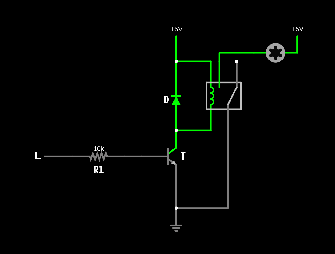 Fan’s controller circuit with BJT transistor
Here the L is a logic source from our GPIO pin, while 5V and GND are power pins from Raspberry Pi. The Motor here indicates a motor located in a fan.
This circuit uses a BJT transistor
Tand a diodeDfor flyback protection. To use a MOSFET transistor, some minor changes must be made (see example below). A diode is required here because the relay builds up energy in its coil. Without this diode, the transistor would be exposed to the inductive current, which would most likely damage it.
When the logic on a GPIO pin is HIGH, relay is being activated and the current can flow freely to the fan (motor). Here is the activated state, when the GPIO pin goes HIGH:
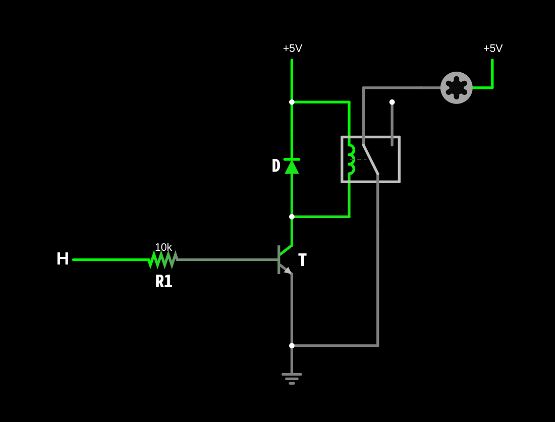 Fan’s controller circuit with BJT transistor (HIGH state)
The R1 resistor limits the base current to a safe value for the GPIO pin and ensures that the transistor operates in the saturation region when turned on.
Here is the link to the circuit simulation with BJT transistor.
The collector of D is connected to one terminal of the inductive load. The other terminal of the load is connected to the positive power supply. When D is turned on, current flows from the collector to the emitter, powering the load. The emitter of is connected directly to ground. This completes the circuit when the transistor is turned on.
What About a MOSFET One
Below is the same circuit, utilizing a MOSFET transistor instead:
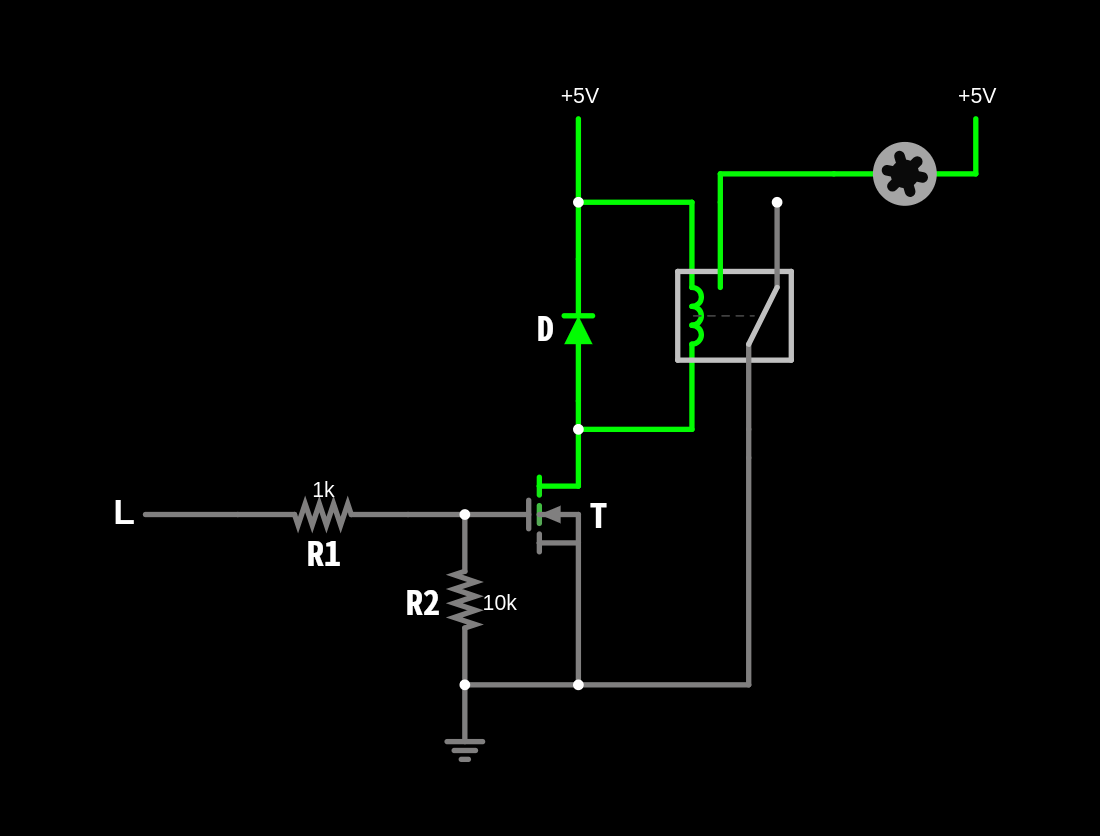 Fan’s controller circuit with MOSFET transistor
Several adjustments are required:
- The gate resistor
R1is placed between the GPIO pin and the gate of the MOSFET. It limits the current flowing into the gate, protecting the GPIO pin from excessive current draw. It also helps to dampen any oscillations that may occur due to the capacitive nature of the MOSFET gate. - The pull-down resistor
R2is connected between the gate of the MOSFET and ground. It ensures that the gate is pulled to ground (LOW) when the GPIO pin is not actively driving it. Without this resistor, the gate could float, leading to unpredictable behavior of the transistor, which is not the case with BJT, and potentially turning the fan on or off unexpectedly
Here is the link to the circuit simulation with MOSFET transistor.
In the examples above, the supply voltages for the Raspberry Pi and the relay should either be the same or at least share a common ground. This means that the fan can be powered with higher voltages, up to 24V, depending on the specifications of the relay and the diode. This setup can be useful if a more powerful fan is needed for better cooling, where the 5V from the Raspberry Pi would not be sufficient.
Another Option
Instead of tinkering with a custom circuit, one can use an out-of-the-box solution like the KY-019 relay module. This module contains all the necessary components, allowing us to easily switch the fan on and off by simply writing data to our character driver. Below is information about the connection
| KY-019 Relay Module Pins | Description |
|---|---|
| S (Signal) | Control signal input (connects to the GPIO pin on Raspberry Pi) |
| Middle (VCC) | 5V power input |
| G (GND) | Ground |
| Connection | Description |
|---|---|
| Signal Pin (S) to Raspberry Pi GPIO Pin | Connect the S pin of the KY-019 relay module to a GPIO pin on the Raspberry Pi. |
| VCC to 5V Pin | Connect the VCC pin of the KY-019 relay module to the 5V power pin on the Raspberry Pi. |
| GND to GND Pin | Connect the GND pin of the KY-019 relay module to a GND pin on the Raspberry Pi. |
| Fan Connections | - Connect one terminal of the fan to the normally open (NO) pin of the relay. |
| - Connect the other terminal of the fan to the 5V power supply. | |
| - Connect the common (COM) pin of the relay to the GND. |
After connecting everything properly, here are the results:

The circuit will also work with PWM, which will be covered in future posts. According to oscilloscope data, the voltage on the fan is 4V, which is lower than the expected 5V, but it is still quite stable for a breadboard setup.
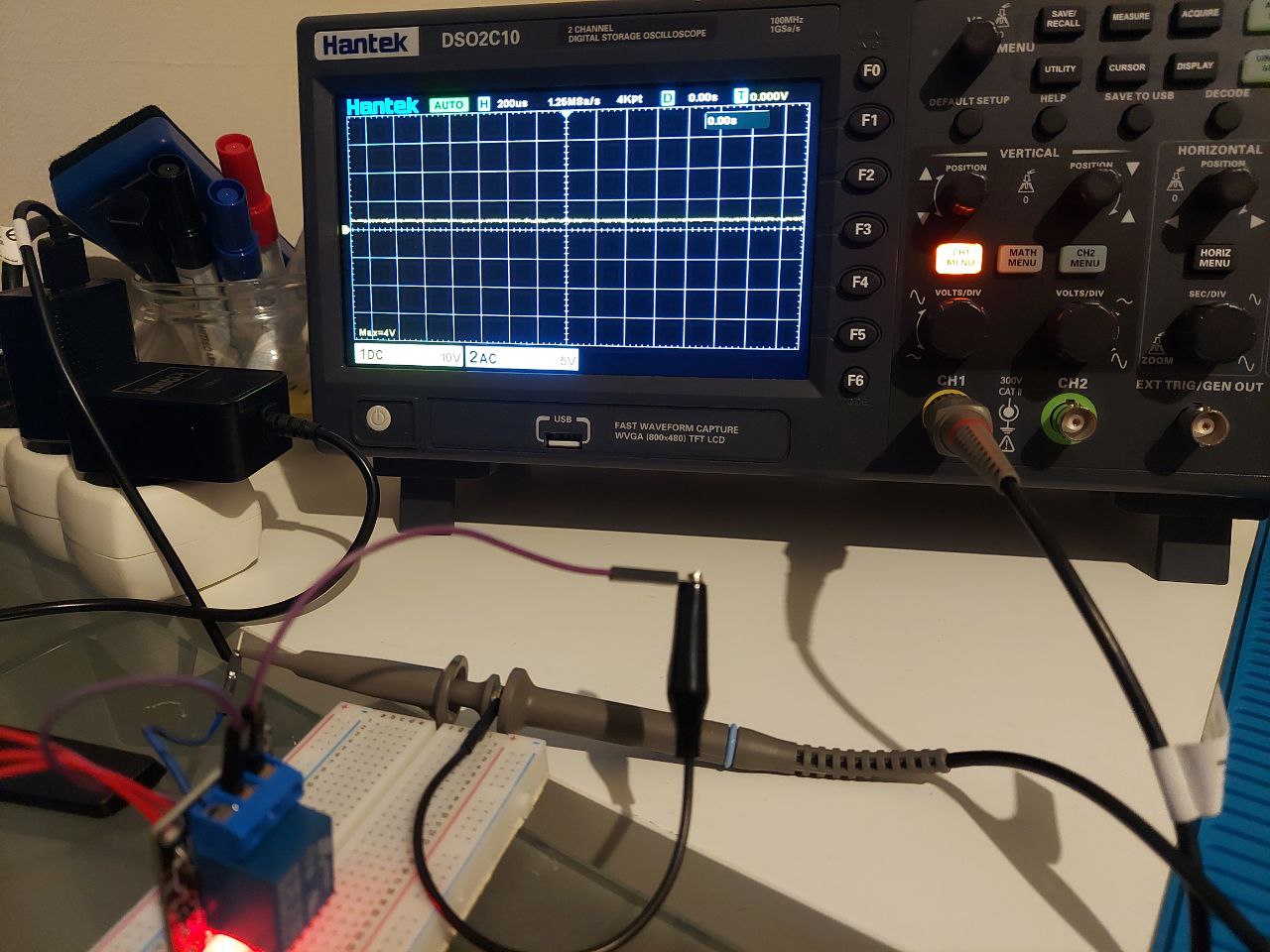 Voltage measured on the circuit’s output
In the next part, PWM support will be implemented. Since most kernels do not support the legacy function for obtaining a PWM chip, it is necessary to implement a proper device-tree overlay to access this chip and make it configurable on different channels.
Read more
Footnotes:
While this header can be found on most Raspberry Pi devices, the header is unpopulated (has no headers) on Zero and Pico devices that lack the “H” suffix. ↩︎
To read it, you first must be sure that the
debugfsis mounted:mount -t debugfs zero /sys/kernel/debug. After that we can simplycatthe data out:cat /sys/kernel/debug/gpio. ↩︎They do work with numbers:
0 ... 999, labelsMIN ... MAXand even characters'A' ... 'Z'. ↩︎
Comments powered by Disqus.